Acquiring an Injection Molding Machine represents a high-stakes capital investment where specification errors directly impact unit economics, cycle times, and overall profitability. Matching machine specifications like tonnage, drive type, and shot capacity to specific production requirements is notoriously difficult. Manufacturers often struggle to balance part geometry, material properties, and annual volume without overcapitalizing or creating production bottlenecks. You need a rigorous approach to evaluate equipment capabilities against your actual shop floor realities. This technical evaluation framework is designed to help manufacturing leaders and procurement engineers assess, shortlist, and select the optimal injection molding equipment. By focusing on hard performance data, mechanical architecture, and facility integration, you can lock in a machine configuration that handles your specific resin grades and mold designs efficiently. We will break down the core mechanics, drive technologies, and sizing calculations necessary to make an informed equipment selection.
- Drive Type Dictates Efficiency: The choice between hydraulic, all-electric, and hybrid machines fundamentally alters energy consumption, precision, and maintenance schedules.
- Tonnage is Not Arbitrary: Accurately calculating clamping force requirements based on part projected area and material flow prevents flash defects and premature mold wear.
- Long-Term Profitability Extends Beyond CapEx: Long-term profitability relies on factoring in cycle time reductions, energy costs, scrap rates, and integration with secondary automation.
- Facility Readiness is Critical: Implementation success requires upfront validation of power drops, chilled water systems, and floor loading capacities before machine delivery.
Core Architecture: Understanding the Equipment
The Injection Unit (Melting and Delivery)
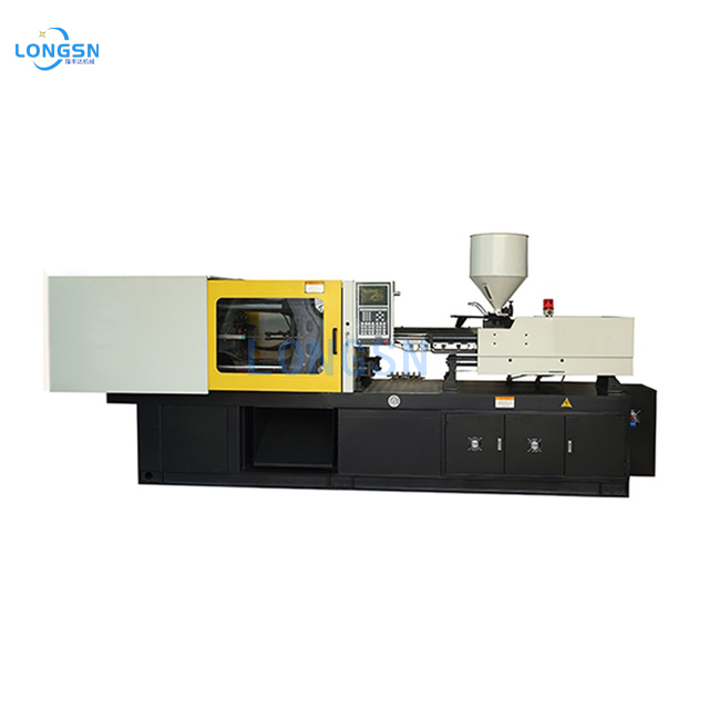
The injection unit melts raw plastic pellets and forces the molten material into the mold cavity under extreme pressure. It consists of a material hopper, a heated barrel, and a reciprocating screw. The hopper gravity-feeds raw resin into the feed zone of the barrel. External heater bands wrap around the barrel to provide initial heat, but the reciprocating screw generates the majority of the thermal energy. As the screw rotates, it shears the plastic pellets against the barrel wall. This mechanical friction creates shear heating, which melts the polymer chains efficiently.
Screw design dictates melt homogeneity and prevents material degradation. A standard general-purpose screw features three distinct zones: feed, transition (compression), and metering. The feed zone conveys solid pellets. The transition zone compresses the melting plastic, forcing out trapped air. The metering zone ensures a uniform melt temperature before injection. Processing heat-sensitive resins like PVC requires a low-compression screw to prevent burning, while crystalline materials like nylon need a sharp transition zone to handle sudden melting points. The non-return valve, or check ring, sits at the tip of the screw. It allows plastic to flow forward during recovery but seals shut during injection, acting as a piston to push the shot into the mold.
The Clamping Unit (Mold Actuation and Force)
The clamping unit holds the heavy steel mold halves, opens and closes them rapidly, and provides the massive force required to keep the mold shut during injection. It consists of a stationary platen holding the cavity side of the mold and a moving platen holding the core side. Heavy steel tie bars guide the moving platen and stretch slightly under load to generate clamping force.
Toggle clamp mechanisms utilize mechanical linkages to multiply the force generated by a smaller hydraulic cylinder or electric motor. When the toggle links straighten and lock over center, they provide immense, rigid clamping force. Toggles offer rapid opening and closing speeds, making them ideal for fast-cycle packaging applications. However, they require continuous lubrication and precise stroke adjustment to accommodate different mold heights. Direct hydraulic ram systems use a massive hydraulic cylinder to push the moving platen directly. They offer infinite stroke adjustment, uniform force distribution across the platen, and exact tonnage control. While generally slower than toggles, direct hydraulic clamps excel in deep-draw parts and heavy automotive molding where platen deflection must be minimized.
Control Systems and Interfaces
Modern equipment relies on advanced Human-Machine Interface (HMI) systems rather than legacy analog dials and closed-loop relays. These controllers process thousands of data points per second, allowing technicians to set precise velocity profiles, pressure transfers, and temperature PID loops. The controller screen displays real-time graphs of injection pressure versus screw position, which is critical for diagnosing short shots or flashing.
Real-time monitoring maintains process capability. The controller tracks variables like plasticizing time, cushion size, and peak injection pressure. If the cushion drops to zero, the machine alerts the operator that the check ring may be leaking or the barrel is starved of material. Advanced systems integrate directly with auxiliary equipment, allowing the main HMI to control mold temperature controllers, hot runner systems, and part-picking robots from a single screen.

The Injection Molding Cycle: How the Machine Operates
The Six-Stage Machine Sequence
The molding cycle is a continuous, repeatable sequence of mechanical and thermal events. Every fraction of a second matters when optimizing for high-volume production.
- Clamping: The moving platen advances, and the clamping mechanism builds full tonnage. The mold must be completely sealed to withstand cavity pressures that can exceed 10,000 psi.
- Injection: The reciprocating screw stops rotating and drives forward linearly. It pushes the accumulated melt pool through the nozzle, sprue, runners, and gates into the mold cavities. This phase is velocity-controlled.
- Dwelling (Holding Pressure): Once the cavities are nearly full, the machine switches from velocity control to pressure control. It holds pressure on the melt to pack out the part, compensating for volumetric shrinkage as the plastic cools against the chilled mold walls.
- Cooling & Plastification: The gate freezes off, isolating the part from the barrel. The part continues cooling in the mold. Simultaneously, the screw rotates and retracts, drawing in new pellets and melting the next shot.
- Mold Opening: The clamp releases tonnage and retracts the moving platen. The speed profile starts slow to break the vacuum, accelerates for speed, and decelerates to stop smoothly.
- Ejection: Hydraulic or electric ejector rods push the mold's ejector plate forward. Ejector pins knock the rigid part off the core, allowing it to fall onto a conveyor or be retrieved by a robot.
Cyclic vs. Continuous Production
Injection molding is a cyclic, high-pressure process designed to create discrete, complex three-dimensional parts. The material is injected into a closed, pressurized void, allowed to solidify, and then extracted. Extrusion is a continuous, lower-pressure process. An extruder continuously forces molten plastic through a shaped die to create 2D profiles like pipes, tubing, weather stripping, or sheet film. You cannot mold a hollow bottle or a complex gear using standard extrusion, just as you cannot continuously output miles of PVC pipe using an injection press.
Evaluating Drive Technologies: Hydraulic, Electric, and Hybrid
Hydraulic Equipment
Hydraulic presses have dominated the shop floor for decades. They utilize a large electric motor to drive a hydraulic pump, which circulates pressurized oil to various cylinders and motors. They deliver massive clamping forces and handle harsh, dirty environments well. Hydraulic machines are the standard for heavy-tonnage applications, such as molding automotive bumpers or large refuse bins.
The primary trade-off is energy inefficiency. Standard hydraulic pumps run continuously, even during idle phases like cooling, dumping excess pressurized oil over relief valves. They also require extensive maintenance. You must filter the hydraulic oil, monitor it for degradation, and periodically replace hundreds of gallons. Leaking hoses and blown seals create slip hazards and contaminate cleanroom environments.
All-Electric Equipment
All-electric presses replace hydraulic pumps and cylinders with independent, direct-drive servo motors and ball screws for every axis of motion. This architecture provides extreme precision and repeatability. Because each movement is independent, electric machines can overlap functions—like ejecting the part while the mold is still opening—shaving valuable seconds off the cycle time.
Electric presses consume up to 70% less energy than standard hydraulic models because the servo motors only draw power when actively moving a load. They operate quietly and eliminate the risk of oil leaks, making them mandatory for medical cleanroom molding. The downside is a higher initial capital expenditure. Furthermore, electric ball screws can wear out prematurely if subjected to continuous, extreme holding pressures for thick-walled parts.
Hybrid Equipment
Hybrid presses combine the heavy-duty clamping force of hydraulics with the precision and speed of electric injection. A common configuration uses a hydraulic clamping unit paired with an electric servo-driven injection unit and an electric screw drive.
This setup is ideal for thick-walled parts that require massive, sustained holding pressure. The hydraulic clamp holds the mold shut effortlessly, while the electric injection unit delivers the shot with pinpoint accuracy. Hybrids offer a practical middle ground, providing better energy efficiency than fully hydraulic machines without the premium price tag of large-tonnage all-electric models.
Sizing Your Equipment: Critical Specifications
Calculating Required Clamping Force (Tonnage)
Selecting the correct tonnage prevents flash and protects the mold. If the injection pressure exceeds the clamping force, the mold halves will separate slightly, allowing plastic to leak across the parting line. The baseline formula is: Projected Area (sq. in.) × Cavity Pressure (tons/sq. in.) = Required Tonnage.
Projected area is the shadow the part would cast if a light shone directly down the axis of mold opening. Cavity pressure depends heavily on material viscosity and part thickness. Easy-flowing materials like Polystyrene might require 2 tons per square inch of projected area. Stiff, viscous engineering resins like Polycarbonate or glass-filled Nylon can demand 4 to 5 tons per square inch. Always calculate the total projected area, including the runner system, and add a 20% safety margin to the final tonnage requirement.
Typical Cavity Pressure Multipliers by Material | Material Type | Viscosity Level | Tons per Square Inch (Estimated) |
| Polystyrene (PS) | Low | 1.5 - 2.0 |
| Polypropylene (PP) | Low to Medium | 2.0 - 2.5 |
| ABS | Medium | 2.5 - 3.0 |
| Polycarbonate (PC) | High | 3.5 - 5.0 |
Shot Size and Injection Capacity
Shot size is the maximum volume or weight of plastic the machine can inject in one cycle. You must match the barrel capacity to your specific mold. Industry best practice dictates utilizing between 20% and 80% of the barrel's maximum capacity per shot.
If you use less than 20% of the barrel capacity, the plastic pellets sit inside the heated barrel for too many cycles. This excessive residence time causes the polymer chains to degrade, leading to brittle parts, color shifts, or splay defects. If you use more than 80% of the capacity, the screw does not have enough stroke left to maintain a proper cushion. Without a cushion, you cannot apply holding pressure, resulting in sink marks and short shots.
Tie-Bar Spacing and Platen Dimensions
Tonnage and shot size mean nothing if the mold physically cannot fit inside the press. Tie-bar spacing dictates the maximum width and height of the mold base. The mold must slide between the four steel tie bars during installation. Always check the horizontal and vertical clearance.
Daylight opening is the maximum distance between the stationary and moving platens when the press is fully open. Maximum stroke is how far the moving platen can travel. Deep-draw parts, like five-gallon buckets or trash cans, require massive daylight and stroke. The press must open wide enough to clear the core, clear the molded part, and allow a robot arm to enter and extract the part without crashing.
How Part Design Influences Machine Demands
Part geometry dictates the required injection speed and pressure capabilities. Thin-wall packaging, like yogurt containers, requires extreme injection velocities. The plastic must fill the entire cavity in a fraction of a second before it freezes against the cold mold steel. This requires high-end accumulators on hydraulic machines or oversized servo motors on electric presses.
Thick-walled parts, like optical lenses or structural brackets, require slow injection speeds but massive, sustained holding pressures to prevent sink marks as the thick sections shrink. Parts with zero draft angles or complex undercuts require high-force hydraulic ejector systems to strip the part off the core without distortion.
Material Compatibility and Processing Capabilities
Commodity Plastics vs. Engineering-Grade Thermoplastics
Processing high-temperature engineering resins like PEEK, PEI (Ultem), or PPS requires specialized hardware. Standard barrels and screws will warp, degrade, or fail under the extreme temperatures required to melt these polymers, which often exceed 700°F (370°C). You need bimetallic barrels lined with tungsten carbide and specialized high-watt-density ceramic heater bands to reach and maintain these temperatures.
Crystalline materials (Nylon, Acetal, Polyethylene) have a sharp melting point and require high energy input to melt. They also shrink significantly during cooling, demanding precise mold temperature control and extended holding pressure. Amorphous materials (Polycarbonate, ABS, Polystyrene) soften gradually and shrink less, but they are highly susceptible to shear stress and require careful velocity profiling to prevent molded-in stress.
Advanced Molding Techniques and Configurations
Standard single-shot molding covers most applications, but complex parts require specialized machine configurations.
- Two-Shot (Multi-Component) Molding: Requires a press with two independent injection units and a rotating center platen. It molds a rigid substrate and then overmolds a soft-touch grip in the same cycle.
- Insert Molding: Often utilizes vertical clamp presses. Operators or robots load metal inserts (like threaded brass nuts) into the open mold before the plastic is injected around them.
- Micro-Molding: Requires specialized micro-injection units with plunger systems rather than standard screws. These presses mold microscopic medical components weighing fractions of a gram, where standard barrels would cause instant material degradation.
Implementation Risks and Mitigation Strategies
Facility Infrastructure Requirements
Purchasing a press that exceeds your facility's utility capacity will halt your project immediately. Before issuing a purchase order, audit your electrical service. Verify you have the correct voltage (typically 460V or 480V 3-phase) and sufficient amperage overhead to handle the machine's peak draw during startup.
Evaluate your chilled water system. The press requires dedicated cooling water for the feed throat, the hydraulic heat exchanger, and the mold itself. Ensure your cooling tower or chiller can handle the additional BTU load. Finally, verify your concrete floor thickness and overhead crane capacity. A 500-ton press weighs tens of thousands of pounds and requires heavy rigging equipment for installation.
Supply Chain and Lead Times
Misalignment between machine delivery and mold tooling completion causes severe production delays. Standard machine lead times range from 12 to 24 weeks, while custom-built high-tonnage presses can take over a year. Synchronize the equipment delivery schedule with your toolmaker's timeline. Ensure the press is installed, leveled, wired, and plumbed before the mold arrives for initial sampling.
Operator Training and Safety Compliance
Modern presses are highly complex and dangerous if operated incorrectly. Bypassing safety gates or overriding limit switches can result in crushed limbs or fatal injuries. Mandate OEM-led training for your setup technicians and operators. They must understand the specific controller interface, alarm codes, and mechanical safety drop bars. Ensure the equipment complies with all local safety standards, including ANSI B151.1 requirements for plastics machinery.
Conclusion
Selecting the optimal equipment depends entirely on the intersection of part geometry, material science, and production volume. Define the part and material, calculate tonnage and shot size, select the drive type based on precision and energy needs, and evaluate OEM support. Do not guess on specifications; use the data from your mold design to drive the machine requirements.
Engage with two or three machine OEMs to run a physical mold trial using your actual production tooling and resin. Request a detailed energy consumption estimate based on your specific cycle time to accurately forecast operational costs. Verify local service technician availability and spare parts inventory to ensure prompt support and minimize potential downtime.
FAQ
Q: What is the average lifespan of an injection molding machine?
A: The expected lifecycle is typically 15 to 20 years in a continuous production environment. This lifespan is highly contingent on diligent preventative maintenance, proper oil filtration, and avoiding consistent operation at maximum tonnage limits.
Q: How do I choose between a hydraulic and an electric injection molding machine?
A: Base your decision on your specific application. Choose electric for high precision, fast cycle times, lower energy consumption, and cleanroom requirements. Choose hydraulic for massive clamping force, deep-draw parts, and lower initial capital expenditure.
Q: What does "tonnage" mean in injection molding?
A: Tonnage refers strictly to the maximum clamping force the machine can exert to keep the mold closed against the internal pressure of the molten plastic during the injection and packing phases.
Q: Can one injection molding machine run different types of plastics?
A: Yes, but it requires thorough purging procedures to remove the previous resin. You must also ensure the screw geometry is compatible with the new material and verify the heater bands can reach the required processing temperatures.
Q: What is the difference between injection molding and extrusion molding machines?
A: Injection molding creates discrete, three-dimensional parts by forcing plastic into a closed mold cavity. Extrusion continuously pushes molten plastic through an open die to manufacture continuous, two-dimensional profiles like pipes, tubing, or sheet film.

 English