Procuring industrial manufacturing equipment dictates long-term operational capabilities on the factory floor. Selecting the wrong hardware immediately leads to bottlenecked cycle times, excessive scrap rates, and inflated energy consumption. Operations managers and process engineers face the hard engineering challenge of matching specific production requirements—part volume, material melt flow, and precision tolerances—with the exact technical specifications of modern molding equipment. Understanding these mechanical variables prevents catastrophic production failures and ensures consistent part quality.
This technical evaluation framework allows you to objectively compare machine types, drive systems, and critical specifications before finalizing equipment selection. By analyzing clamping forces, injection unit capacities, and control capabilities, you align hardware capabilities directly with your manufacturing floor realities. Whether upgrading an existing cell or building a new production line, evaluating a Injection Molding Machine requires a systematic, data-driven approach to guarantee optimal mechanical performance.
- Drive system selection (hydraulic, electric, or hybrid) dictates up to 70% of long-term energy consumption and directly impacts cleanroom compliance.
- Clamping force (tonnage) and tie-bar spacing must be calculated based on the specific projected area of the largest anticipated mold, plus a 10-20% safety margin.
- Shot size and injection pressure requirements vary heavily by polymer melt flow index; over-speccing leads to material degradation, while under-speccing causes short shots.
Framing the Decision: Core Success Criteria for Plastic Manufacturing
Defining Production Baselines
Establishing accurate production baselines requires a hard audit of current and projected manufacturing metrics. You must evaluate production volumes, required cycle times, and shift structures before looking at hardware specifications. A facility running continuous 24/7 operations demands equipment with heavy-duty linear guides and high-durability ball screws to withstand constant cycling. Conversely, a plant operating single shifts for low-volume custom runs might prioritize rapid mold changeover features over absolute maximum cycle speed. Documenting these baselines ensures the selected machine matches the actual physical demands of your production schedule.
Material and Application Constraints
The specific polymers you process dictate the required barrel temperatures, screw designs, and injection pressures. Thermoplastics, thermosetting polymers, and elastomers all behave differently under shear and heat. High-temperature engineering resins like PEEK or PEI demand specialized ceramic heater bands and robust bimetallic screw metallurgy to prevent premature wear and maintain melt stability. Processing heat-sensitive materials like PVC requires precise thermal control and specific screw geometries to avoid material degradation inside the barrel. Matching the machine's plasticizing capacity to the specific polymer ensures consistent melt quality and structural part integrity.
Process Distinctions
You must distinguish the discrete, high-pressure process of injection molding from continuous extrusion systems. Injection molding forces molten plastic into a closed, high-pressure mold cavity to form complex, three-dimensional parts with tight tolerances. Extrusion pushes material continuously through a die to create linear profiles like pipes, weather stripping, or sheets. Establishing these absolute scope boundaries ensures you evaluate the correct mechanical technology for your specific part geometry and production method.
Quality and Tolerance Mandates
Industry-specific compliance forces strict requirements for machine repeatability and environmental compatibility. Medical device manufacturing governed by ISO 13485 often requires all-electric machines to eliminate aerosolized oil contamination risks and ensure precise dimensional tolerances for surgical components. Automotive applications under IATF 16949 demand high repeatability to maintain tight clearances in complex under-hood assemblies. Your specific quality mandates dictate the level of closed-loop precision, sensor feedback, and control required from the molding equipment.
Anatomy of an Injection Molding Machine: Core System Components
The Injection Unit
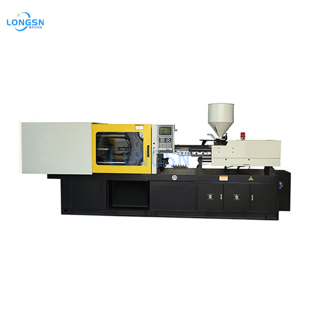
The injection unit melts, homogenizes, and conveys the polymer into the mold. It starts with the hopper, which feeds raw plastic pellets into the heated barrel. Inside the barrel, a reciprocating screw rotates to shear and melt the plastic, moving it forward into the accumulation zone. Heater bands wrapped around the barrel provide supplemental heat to maintain the correct melt temperature profile across different zones. The nozzle acts as the final interface, seating against the mold sprue bushing and injecting the molten polymer into the cavity under extreme pressure.
The Clamping Unit
The clamping unit holds the heavy steel tooling halves together under immense pressure during the injection and solidification phases. It utilizes either a mechanical toggle mechanism or a direct hydraulic ram system. Toggle clamps use a series of linkages to multiply force, offering fast movement and mechanical lock-up, making them highly suitable for high-speed, thin-wall operations. Hydraulic rams provide direct, variable control over clamping force and superior mold protection, which is highly beneficial for complex, delicate tooling setups or parts requiring precise venting.
The Mold / Tooling Interface
The mold interface dictates machine compatibility with your existing tooling portfolio. Key physical features include locating rings, which ensure the mold centers perfectly with the machine's injection nozzle to prevent leaks. Ejector pin interfaces must align exactly with the machine's knockout patterns to facilitate automated part removal. Cooling line manifold connections must be easily accessible to manage mold temperatures effectively, ensuring optimal cycle times and preventing part warpage during the cooling phase.
The Control System Console
The control system console acts as the operational brain of the equipment. It coordinates pressure, speed, temperature, and auxiliary automation triggers in real-time. Modern controllers offer intuitive touchscreens, allowing setup technicians to set precise parameters and monitor live process data. Advanced systems provide closed-loop feedback, automatically adjusting injection speeds and hold pressures to maintain consistent part weight and alert operators to process deviations before defective parts are produced.

Classifying the Injection Molding Machine: Drive Systems Compared
Hydraulic Injection Molding Machines
Hydraulic machines rely on centralized hydraulic fluid, directional valves, and heavy-duty pumps to generate high clamping forces and drive injection mechanisms. They are the standard for manufacturing heavy, thick-walled parts and applications requiring massive tonnage. These machines offer robust durability in harsh, dirty environments and high resistance to mechanical wear and tear. The hydraulic accumulator systems can be configured to deliver massive bursts of injection speed when required for specific part geometries.
Hydraulic systems have notable mechanical trade-offs. They consume significantly more energy because the pump motor often runs continuously, even during idle phases of the cycle. The reliance on pressurized hydraulic oil introduces the constant risk of fluid leaks and aerosolized mist, rendering them unsuitable for strict cleanroom environments. Hydraulic pumps and proportional valves also generate higher ambient noise levels on the production floor.
All-Electric Injection Molding Machines
All-electric machines utilize independent, high-torque servo motors for each distinct machine function, including injection, plasticizing, clamping, and ejection. This direct-drive design is ideal for high-precision, thin-walled, and medical-grade components. They offer extreme precision and shot-to-shot repeatability, ensuring consistent part dimensions. Electric machines consume up to 70% less energy than hydraulic models because motors only draw power when actively moving. They carry zero risk of oil contamination.
Independent servo motors allow for overlapping parallel movements—such as ejecting a part while simultaneously rotating the screw to build the next shot—resulting in faster overall cycle times. The primary limitation is lower maximum clamping force availability compared to massive hydraulic units, restricting their use for extremely large automotive or structural parts. Maintenance requires technicians skilled in digital drives and servo tuning rather than fluid power.
Hybrid Injection Molding Machines
Hybrid machines combine an electric screw drive for precise, energy-efficient material preparation with a hydraulic clamp for high-force closure. This configuration targets medium-to-large parts requiring both precision and raw power. Hybrids balance the energy efficiency and parallel processing speed of electrics with the high-tonnage capabilities of hydraulics. They offer improved precision over pure hydraulic machines while maintaining the ability to handle demanding, heavy-duty clamping requirements.
The main trade-off is increased mechanical complexity. Maintaining a hybrid machine requires a maintenance department skilled in both hydraulic fluid power systems and electrical servo drives. This dual requirement complicates troubleshooting procedures and increases the reliance on specialized vendor support or highly trained internal maintenance staff to keep the machine running at peak efficiency.
| Drive System | Primary Mechanism | Best Use Cases | Key Mechanical Trade-offs |
| Hydraulic | Fluid pumps and directional valves | Heavy, thick-walled parts, massive tonnage | Higher energy use, slower cycles, oil leak risk |
| All-Electric | Independent servo motors and ball screws | High-precision, thin-walled, cleanroom | Lower maximum tonnage limits, specialized servo maintenance |
| Hybrid | Electric plasticizing, hydraulic clamping | Medium/large parts needing precision and power | Increased mechanical complexity, dual-discipline maintenance |
Critical Specifications and Evaluation Dimensions
Clamping Force (Tonnage) and Platen Dimensions
Calculating the required tonnage prevents flash and dimensional instability. Selecting a machine with inadequate tonnage allows the mold halves to separate slightly during high-pressure injection, causing material to leak and form flash. Physical mold dimensions dictate platen size requirements, specifically tie-bar spacing and maximum daylight. The mold must physically fit between the tie bars for installation. Tie-bar-less machine designs offer significant operational benefits for oversized or complex molds, allowing for easier overhead crane access and accommodating larger tooling without requiring a massive increase in overall machine tonnage.
- Calculate the projected area of the part and runner system in square inches.
- Determine the required cavity pressure based on the material's melt flow index and part wall thickness (typically ranging from 2 to 5 tons per square inch).
- Multiply the projected area by the cavity pressure to find the baseline tonnage.
- Add a 10-20% safety margin to accommodate process variations and ensure consistent clamping performance.
Injection Unit Specs: Shot Size, Pressure, and Screw Design
Shot capacity must be strictly matched to part weight. A standard engineering rule is to utilize 20% to 80% of the machine’s maximum shot capacity. Using less than 20% capacity increases residence time inside the heated barrel, leading to severe polymer degradation and brittle parts. Using more than 80% capacity risks incomplete fills, short shots, and inconsistent recovery times. Injection pressure and speed requirements correlate directly with the material's melt flow index and the part's wall thickness. Thin-walled parts require extremely high injection speeds and pressures to fill the cavity before the material freezes off.
The screw Length-to-Diameter (L/D) ratio impacts melt homogeneity. A higher L/D ratio (e.g., 25:1) provides more residence time for melting and mixing, which is crucial for engineered resins heavily loaded with additives, glass fibers, or colorants. Selecting the appropriate screw profile—specifically the compression ratio—ensures consistent melt quality, reducing visual defects and improving the mechanical properties of the final molded part.
Tooling Compatibility, Gate Design, and Surface Finishes
Integrating hot or cold runner systems requires specific machine control capabilities. The machine controller must manage integrated hot runner temperature zones, pneumatic valve gate sequences, and auxiliary hydraulic core pulls. Seamless integration ensures precise timing and control over material flow, reducing waste and improving part quality. Surface finish optimization demands high-injection-speed capabilities and precise barrel temperature control. These features are mandatory for achieving premium surface finishes, such as SPI-A1 high polish, and avoiding cosmetic defects like splay, flow marks, or knit lines.
Control Systems and Automation Integration
Modern software capabilities are essential for efficient operation and quality control. Closed-loop control systems provide real-time monitoring and adjustment of injection pressure, barrel temperature, and screw position, ensuring consistent process stability across thousands of cycles. Industry 4.0 interoperability features, such as OPC UA compatibility, enable centralized data collection and predictive maintenance tracking. Seamless integration with external robotics, including pneumatic sprue pickers and 6-axis robotic arms, facilitates automated part removal, insert loading, and downstream processing, significantly increasing overall production efficiency.
Implementation Risks and Mitigation Strategies
Facility Requirements and Infrastructure Upgrades
Installing new molding equipment requires rigorous facility preparation. You must address footprint and workflow spatial requirements before the machine arrives. Ensure adequate clearance for mold changes, overhead crane access, and downstream automation equipment to maintain a safe and efficient production environment.
- Verify electrical drops can handle the high-amperage draw of servo motors or large hydraulic pump motors.
- Audit the concrete foundation thickness; high-tonnage machines require reinforced pads to prevent settling and maintain platen alignment.
- Calculate the required cooling water flow rate (GPM) and pressure to support the machine's heat exchanger and the mold's cooling channels.
- Ensure compressed air lines deliver clean, dry air at the correct CFM for pneumatic valve gates and robotic end-of-arm tooling.
Operator Training and Change Management
Transitioning a workforce from legacy hydraulic systems to highly digitized, software-driven electric machines introduces significant skill gaps. Operators and maintenance personnel must adapt to new digital interfaces, closed-loop tuning parameters, and advanced troubleshooting procedures. Recommend negotiating comprehensive, on-site vendor training programs as part of the procurement contract. Access to digital twin simulation accelerates the learning curve, allowing operators to familiarize themselves with the new controls and alarm codes before running live production.
Conclusion
There is no universal machine for every application; the optimal choice requires strict mathematical alignment between part specifications, facility constraints, and production timelines. Default to electric machines for cleanroom environments and high-precision requirements. Select hydraulic machines for massive tonnage needs. Opt for hybrid systems for high-throughput, thick-walled applications requiring a balance of power and precision.
- Compile a detailed Request for Proposal (RFP) that includes specific mold data, material data sheets, and target cycle times.
- Conduct a thorough facility audit to identify necessary electrical, cooling, and foundation infrastructure upgrades.
- Present the comprehensive RFP to shortlisted equipment manufacturers to ensure accurate machine sizing and specification matching.
- Require vendors to provide detailed layout drawings to verify the machine and auxiliary equipment fit within your designated floor space.
FAQ
Q: How do I calculate the required tonnage for an injection molding machine?
A: Calculate tonnage by multiplying the projected area of the part and runner system (in square inches) by the required cavity pressure (tons per square inch) for the specific material. Always add a 10-20% safety margin to accommodate process variations and ensure consistent clamping force without flashing.
Q: What is the difference between shot size and injection capacity?
A: Shot size refers to the actual deliverable plastic weight for a specific mold, dependent on the material's specific gravity. Injection capacity is the theoretical maximum volumetric displacement of the injection unit, usually measured in ounces or cubic centimeters of general-purpose polystyrene.
Q: Why do all-electric injection molding machines require specialized components?
A: All-electric machines utilize high-torque servo motors, advanced closed-loop digital controllers, and precision ball screws for each independent machine movement. These specialized components replace the centralized hydraulic pump and valve system, requiring different maintenance disciplines and digital troubleshooting skills.
Q: Can a hydraulic machine be used in a cleanroom environment?
A: Hydraulic machines are generally unsuitable for strict cleanrooms due to the contamination risks associated with hydraulic oil leaks and aerosolized fluid mist. All-electric machines are the standard for ISO-certified cleanroom environments because they eliminate fluid power entirely.
Q: What is the difference between an injection molding machine and an extrusion molding line?
A: An injection molding machine forces molten plastic into a closed mold under high pressure to create discrete, three-dimensional parts. An extrusion line continuously pushes molten plastic through a die to form continuous linear profiles like pipes, tubes, or flat sheets.

 English