The setup phase of heavy industrial equipment ultimately dictates its entire operational lifespan. Improper installation of a Blow Moulding Machine directly impacts cycle times, compromises product quality, and damages your long-term return on investment. Plant managers face a daunting challenge when new equipment arrives on the factory floor. They must carefully bridge the gap between initial machine delivery and full commercial production. You need to accomplish this transition without compromising stringent safety protocols or missing strict regulatory compliance standards.
Rushing this equipment integration often leads to catastrophic mechanical failures or severe safety hazards down the line. This comprehensive guide provides a rigorous, step-by-step framework for deploying your equipment effectively. Readers will learn exactly how to ensure complete operational readiness and mitigate common rollout risks early in the process. We also outline how you can establish accurate baseline performance metrics from day one.
Key Takeaways
- Facility Readiness is Non-Negotiable: Success begins before delivery, requiring strict adherence to power, pneumatic, and cooling utility specifications.
- Precision Integration: Mechanical leveling and electrical integration must follow certified safety standards (e.g., LOTO protocols, ISO compliance).
- Data-Driven Configuration: Initial parameter setups (temperature profiles, parison control) must be explicitly mapped to the specific resin and mold design.
- Iterative Validation: A systematic dry run and First Article Inspection (FAI) dictate the transition from testing to full-scale, scalable production.
Pre-Installation Readiness: Mitigating Rollout Risks Early
Successful equipment deployment always starts weeks before the delivery truck arrives. Plant managers must evaluate physical infrastructure and secure necessary compliance frameworks in advance. Missing a single utility requirement delays the entire commissioning schedule. You must assess the floor plan rigorously.
Utility and Footprint Assessment
Evaluate space constraints carefully before placing the equipment. You need adequate clearance for operator access, mold changes, and daily maintenance routines. Material handling workflows require seamless integration around the machine perimeter. Forklifts and automated guided vehicles need clear transit lanes. Never crowd the operational footprint.
You must verify industrial utility capacities well in advance. Electrical load stability is critical for sensitive PLC components. Ensure compressed air pressure meets the exact Bar/PSI requirements for your specific production volume. Chilled water flow rates must adequately support rapid mold cooling.
| Utility Category | Specification Focus | Common Pre-Installation Pitfall |
| Electrical | Voltage stability, phase balance, peak amperage. | Ignoring voltage drops during simultaneous motor starts. |
| Pneumatic | Consistent Bar/PSI, dry air filtration (dew point). | Moisture in airlines causing internal mold defects. |
| Cooling | GPM flow rate, chilling capacity (tons), temperature. | Undersized chillers extending cycle times unnecessarily. |
Safety and Compliance Framework
Establish strict Lockout/Tagout (LOTO) protocols prior to uncrating the equipment. Operators and technicians must know exactly where isolation points reside. Lock out the main electrical breakers. Tag every high-pressure pneumatic valve. Zero energy state verification is mandatory before mechanical assembly begins.
Review local environmental regulations thoroughly. OSHA and ISO safety compliance requirements dictate specific rules for handling hydraulic and pneumatic systems. You must ensure spill containment measures exist around hydraulic reservoirs. Install proper guarding around pinch points. Document every compliance check rigorously.
Vendor Alignment
Confirm the exact scope of technical support provided by the manufacturer. You must validate all warranty conditions before turning on the power. Cross-reference the factory acceptance test (FAT) documentation. Ensure it matches the specific delivered unit perfectly. Any discrepancy requires immediate vendor notification.
Mechanical and Utility Integration of the Blow Moulding Machine
Moving from theoretical planning to physical implementation introduces structural realities. You must assemble the framework methodically. Precision matters immensely during this phase. Every bolt and fluid line sets the foundation for future reliability.
Positioning and Leveling
Place the equipment carefully on high-grade, vibration-damping mounts. These mounts isolate the machine from external factory floor vibrations. They also prevent internal mechanical shocks from damaging the surrounding infrastructure. Follow these step-by-step instructions for positioning:
- Lower the machine chassis onto the designated floor footprint.
- Insert the vibration-damping leveling pads under each anchor point.
- Use a precision machinist level across the main platen guides.
- Adjust each mounting pad sequentially until you achieve perfect equilibrium.
- Lock the adjustment nuts securely to prevent drift during operation.
Precision leveling is absolutely critical for mechanical longevity. Uneven placement causes premature wear on the clamping unit. It unevenly distributes immense closing forces across the tie bars. This stress eventually stretches the steel rods, leading to flashing defects and catastrophic mechanical failure.
Connecting Critical Sub-systems
Integrating a Blow Moulding Machine requires seamless utility handshakes. The pneumatics system drives the core blowing process. You must secure all high-pressure air lines tightly. Verify inline filtration systems immediately. Superior filtration prevents moisture and compressor oil from contaminating the finished product interior.
Hydraulics and servo motors power the heavy lifting. Connect the clamping mechanisms carefully. Route the extrusion drive hoses without creating sharp bends. Bleed all air from the hydraulic lines to prevent spongy platen movements. Tighten servo feedback cables to ensure zero signal loss.
Cooling systems control your ultimate production profitability. Hook up the main chiller lines directly to the mold. Connect a secondary cooling circuit to the feed throat. Proper feed throat cooling prevents premature polymer melting. This thermal control ensures highly predictable cycle times.
Electrical Phasing and Grounding
Electrical integration demands extreme caution. First, verify the main motor rotation direction. Running an extruder screw backward causes severe internal damage. Briefly bump the motor starter. Observe the cooling fan rotation to confirm proper phasing.
Ensure proper grounding across the entire chassis. A robust earth ground protects sensitive PLCs from voltage spikes. It also shields the sensitive parison programming controllers from electrical noise. Drive in dedicated grounding rods if facility grounds show excessive resistance.
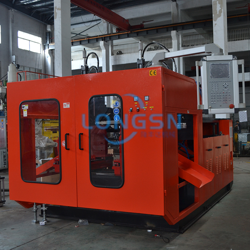
Configuring Core Parameters: Features-to-Outcomes Mapping
Hardware installation only completes half the battle. You must now configure the operational software and thermal profiles. Aligning technical features to specific production outcomes guarantees success. Data-driven parameters separate reliable production from inconsistent scrap generation.
Temperature Profile Setup
Calibrating extruder heating zones requires deep material knowledge. You must base these settings on the specific polymer utilized. Different resins like HDPE, PET, or PP demand vastly different thermal curves. Improper temperatures cause severe material degradation or push unmelted resins through the die head.
| Polymer Type | Feed Zone Temp (°C) | Metering Zone Temp (°C) | Die Head Temp (°C) |
| HDPE | 160 - 175 | 180 - 195 | 185 - 200 |
| PP | 180 - 200 | 210 - 230 | 215 - 235 |
| PET | 260 - 275 | 270 - 285 | 275 - 290 |
Establish a rising temperature profile from the feed throat to the die head. This gradual increase ensures homogeneous melting. It reduces sheer stress on the polymer chains. Always allow the barrel to soak at the set temperature for at least thirty minutes before activating the screw.
Parison Programming and Weight Control
Modern blow moulding relies heavily on precision parison programming. You will utilize the machine’s Wall Thickness Controller (WTC). The WTC manipulates the die gap dynamically as the plastic drops. This creates varying thickness levels along the parison length.
- Identify areas of the product requiring deep stretching (e.g., corners).
- Program thicker parison points corresponding to those stretch zones.
- Identify narrow sections requiring less material.
- Reduce the die gap for these specific profile points.
Translating product specifications into WTC profile points ensures uniform final wall thickness. It eliminates excessive material waste. You save raw resin while improving the structural integrity of the final container. Fine-tuning this profile requires empirical observation.
Clamping Force and Cycle Timing
Protect your expensive tooling by setting a low-pressure mold close phase. The platens should move together swiftly but engage the final inches under low pressure. If an obstruction exists, the machine will abort the close. Apply high-pressure clamping force only after full mold contact.
Calculate initial cooling times based on the mold’s volumetric capacity and wall thickness. Determine optimal blowing pressures. Program the exhaust sequences to release internal air before the mold opens. Precise cycle timing maximizes hourly output without sacrificing dimensional stability.
The Testing Phase: Dry Runs and First Article Inspection (FAI)
Testing bridges the gap between static configuration and dynamic production. You cannot jump directly into full-speed manufacturing. A methodical testing phase validates every previous setup step. It provides verifiable performance metrics before committing valuable raw materials.
The Dry Run (No-Load Test)
Execute a full machine cycle entirely without resin first. This no-load test verifies mechanical clearances safely. Watch the platens open and close. Listen for abnormal grinding noises or hydraulic squeals. Smooth, repeatable motion indicates a successful mechanical build.
Verify all sensor triggers during this dry run. Ensure proximity switches read the platen positions accurately. Test the safety gate interlocks thoroughly. Open the operator gate during a simulated cycle. The machine must halt all hazardous motion instantly. Never bypass these safety checks.
Material Purging and First Extrusion
You must safely purge manufacturing preservation oils from the barrel. Introduce the first batch of virgin resin slowly. Keep extruder RPMs very low. Watch the die head closely as the first plastic emerges. You want to see clear, uncontaminated material flowing smoothly.
Observe the initial parison drop carefully. Look for straightness. A curving parison indicates uneven die head temperatures or physical misalignment. Check the melt consistency. The plastic surface should appear smooth, devoid of unmelted particles or trapped moisture bubbles. Make immediate temperature corrections if necessary.
Evaluating the First Article (FAI)
Capture the first molded unit for First Article Inspection (FAI). You must inspect this initial part for critical defects. Check the parting line for excessive flash. Look for webbing in tight corners. Measure the overall weight to verify the WTC baseline.
Measure the wall distribution using ultrasonic thickness gauges. Inspect the neck finish inaccuracies closely. Adjust the blow pin alignment if the neck inner diameter shows ovality. Re-center the die head concentricity based on these empirical measurements. Iterate this process until you produce a flawless container.
Post-Setup Evaluation: Long-Term Scalability and Vendor Assessment
Achieving one perfect part does not mean the setup is complete. You must secure long-term operational stability. Documenting success ensures anyone can replicate it. This phase focuses on future fleet expansion, operational security, and equipment longevity.
Standard Operating Procedure (SOP) Handover
Document the exact baseline parameters that yielded the approved FAI. Record the temperature zones, WTC profiles, and cycle timers. Create a comprehensive Standard Operating Procedure (SOP) document. This paperwork becomes the technical bible for your specific Blow Moulding Machine.
Train operators immediately on these standardized routines. Walk them through the daily start-up sequence. Teach them the emergency shut-down protocols. Establish strict preventative maintenance routines. Show operators how to grease tie bars, check oil levels, and clean water filters daily.
Assessing Vendor Implementation Support
Evaluate how the manufacturer handled integration hurdles during the setup. Did they provide rapid troubleshooting support? Were the electrical schematics accurate? This assessment serves as a key metric for shortlisting vendors for future equipment purchases. A supportive vendor guarantees higher lifecycle uptime.
Establishing Predictive Maintenance Baselines
Log initial hydraulic pressures under normal load. Record the baseline motor amp draws during extrusion. Document the exact cycle times for the approved part. These baseline metrics create a highly accurate benchmark for future troubleshooting.
If cycle times degrade six months later, you can compare current data against these baselines. If motor amps creep higher, you know the screw may need cleaning. Predictive maintenance relies entirely on capturing pristine data during the initial setup window.
Conclusion
Transitioning from a bare factory floor to an optimized production cell demands extreme discipline. We have explored the critical necessities of facility readiness, mechanical integration, and precise parameter configuration. Bypassing any step invites inconsistent product yields and threatens your capital investment.
A methodical setup process ultimately safeguards the equipment. It ensures structural longevity, thermal stability, and flawless repetitive motion. Thorough dry runs and iterative FAI evaluations eliminate guesswork. You rely on empirical data to drive every adjustment.
Technical teams must now take decisive action. Lock in your optimized parameters securely. Finalize your SOPs and distribute them to all shift operators. Begin tracking your Overall Equipment Effectiveness (OEE) daily. Strong baseline setups guarantee profitable, long-term manufacturing success.
FAQ
Q: How long does it typically take to fully set up and commission a standard blow moulding machine?
A: A standard commissioning timeline usually spans one to three weeks. This duration depends heavily on facility readiness. If electrical, pneumatic, and cooling utilities are pre-installed correctly, mechanical integration takes just days. The remaining time focuses entirely on thermal calibration, parison programming, and producing the first flawless article.
Q: What are the most common reasons for a failed first run during setup?
A: Failed initial runs usually stem from three main issues. Material contamination often occurs if preservation oils aren't fully purged. Uncalibrated die heads cause curved parisons and uneven wall thickness. Inadequate cooling flow rates lead to warped parts because the plastic remains too hot during demolding.
Q: Do I need the manufacturer's technician on-site for the setup?
A: Yes, utilizing an OEM technician is highly recommended. Their presence ensures you do not accidentally void warranty clauses during installation. They provide expert compliance validation and quickly resolve unforeseen integration hurdles. OEM commissioning guarantees the equipment meets factory performance standards from day one.
Q: How do I determine the correct chiller size for my new machine setup?
A: Calculate the required chiller tonnage using a formulaic approach based on maximum material throughput and resin specific heat. You must determine the pounds of plastic processed per hour. Multiply this by the material's cooling requirement (BTUs per pound). Always add a 20% safety margin for ambient factory heat.

 English